|
Electricity section 4: 4.2 A thermistor circuit device - temperature dependent resistor, how it works and its uses [Author © Dr WP Brown PhD: Doc Brown's physics exam revision notes suitable for students of UK IGCSE & GCSE level physics courses, ~ US grades 9-10 physics, electricity page updated Feb 11th 2026 *] [KEY POINTS and learning objectives for this page, after initial notes] [email doc b] * [privacy-policies-disclaimer] * ]SEARCH doc b's science website] INDEX for physics notes on testing circuit devices and how they used
INDEX for physics notes on testing circuit devices and how they used Key points about electric circuits in physics courses - function and use of a thermistor
A structured, exam-board-aligned summary on thermistors, tailored for GCSE/IGCSE Physics students: Thermistors – Summary Revision NotesWhat is a Thermistor?
|


 Circuit
32 shows in principle how to control a cooling fan in a room.
Circuit
32 shows in principle how to control a cooling fan in a room. Footnote
on
Footnote
on | Temperature | Resistance | Explanation |
|---|---|---|
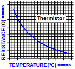
| Low | High | Fewer free electrons → less current |
| High | Low | More free electrons → more current |
This behaviour is non-linear, so thermistors do not obey Ohm’s Law.
Uses of Thermistors
Thermistors are used in circuits where temperature monitoring or control is needed:
- Thermostats (e.g. in ovens, fridges, boilers)
- Fire alarms
- Digital thermometers
- Computer fans (to regulate cooling)
- Battery packs (to prevent overheating)
Required Practical (All Boards)
Aim: Investigate how resistance of a thermistor varies with temperature
Method Overview:
- Connect thermistor in series with ammeter and voltmeter
- Place thermistor in water bath
- Measure resistance at different temperatures using ( R = V/I )
- Plot temperature versus resistance graph
Expected Result: Resistance decreases as temperature increases
Typical Exam Board Specification content involving a thermistor
|
Key Focus |
|---|
| Thermistors as non-ohmic components; required practicals on resistance |
| Emphasis on applications and interpreting resistance–temperature graphs |
| Includes thermistors in component behaviour and practicals |
| Focus on circuit diagrams and temperature-dependent resistance |
| Investigates thermistors in control systems and practical applications |
| Strong emphasis on definitions, graphs, and real-world uses |
Student Tips for a question involving a thermistor
- Memorise: Thermistors are temperature-dependent resistors
- Sketch graphs: Resistance versus temperature is a downward curve
- Use correct terms: “NTC thermistor”, “non-ohmic”, “temperature sensor”
- Explain behaviour: More heat → more free electrons → lower resistance
- Revise practicals: Be confident describing method, apparatus, and expected results
- Think real-world: Link to devices like thermostats and fire alarms
Keywords, phrases and learning objectives for an thermistor device in an electrical circuit
Be able to describe with a circuit diagram, to show how a thermistor device works.
Know that a thermistor is a temperature dependent resistor.
Know examples of what a thermistor is used for e.g. thermostat circuit control, electronic thermometer.
Know the shape of current-voltage curve (I-V graph) for a thermistor.
WHAT NEXT?
INDEX for physics notes on testing circuit devices, how they used - thermistor, LDR, LED and diode
ALL my electricity and magnetism notes
email doc brown - comments - query?
Basic Science Quizzes for UK KS3 science students aged ~12-14, ~US grades 6-8
Biology * Chemistry * Physics for UK GCSE level students aged ~14-16, ~US grades 9-10
Advanced Level Chemistry for pre-university age ~16-18 ~US grades 11-12, K12 Honors
Find your GCSE/IGCSE science course for more help links to all science revision notes
INDEX for physics notes on testing circuit devices and how they usedExplaining the importance of circuit for testing a thermistor device in GCSE level physics, What you need to know about circuit for testing a thermistor device for GCSE level physics, Explaining what is the use of circuit for testing a thermistor device knowledge in GCSE level physics, Examples of circuit for testing a thermistor device explained when studying GCSE level physics, What is the significance of circuit for testing a thermistor device in GCSE level physics, Describing and explaining the theory of circuit for testing a thermistor device when studying GCSE level physics, revision notes for circuit for testing a thermistor device in exams, online exam help for circuit for testing a thermistor device, revision notes for circuit for testing a thermistor device, what do I need to learn about circuit for testing a thermistor device for by GCSE physics exam? revision summary for circuit for testing a thermistor device, help in teaching circuit for testing a thermistor device, learning notes for circuit for testing a thermistor device, help to understand the circuit for testing a thermistor device topic in preparation GCSE physics exam question, how to prepare for questions involving circuit for testing a thermistor device in a GCSE physics examination?
Based on the syllabus-specifications for students taking the IGCSE/GCSE level physics examinations summary revision notes and key points on circuit & uses of a thermistor device for students taking the AQA igcse/gcse physics notes on circuit & uses of a thermistor device, Edexcel gcse physics notes on circuit & uses of a thermistor device, OCR 21st century GCSE physics notes on circuit & uses of a thermistor device, OCR gateway GCSE physics notes on circuit & uses of a thermistor device, WJEC gcse physics notes on circuit & uses of a thermistor device, CCEA gcse physics notes on circuit & uses of a thermistor device for students taking CIE Cambridge igcse physics, or any other GCSE or IGCSE level physics exams notes on circuit & uses of a thermistor device, useful for US grade 9-10 physics coursesSITEMAP Website content © Dr Phil Brown 2000+. All copyrights reserved on Doc Brown's physics revision notes, images, quizzes, worksheets etc. Copying of website material is NOT permitted. Exam revision summaries and references to GCSE science course specifications are unofficial.
